- News & Updates
- 6 years ago

It was just like any other busy Tuesday at Care Systems Services Ltd., where ALC tech Connel Tauber was working on Web Control graphics for a project and Sales & Marketing Manager, Ryan Cramer, was working on the “It’s the Way We Work” quality initiative. The day was forecast to be 36°C and Environment Canada was delivering on its promise.
The town had experienced a power outage the night before and one of our CPA (Contractual Performance Agreement) customers were struggling to get their BAS (Building Automation System) back up and running on their own. The day was heating up and so was their building.
The customer had tried all of the logical steps to recover the system, but the zone controllers just did not report back as online. At 9:06 AM they called for help. Sales & Marketing manager, Ryan Cramer took action and logged onto their Web Control system immediately to see what was going on. At first glance he could see that the zones on the Floor Plan Thermographic view were Pink . A Pink colored zone means that the controllers are not communicating back to the local Web Control server. He knew exactly what he needed to do and launched the Root Cause Failure Analysis technique called Failure Mode Effect Analysis.
Using a Fish Bone diagram takes into consideration factors such as the People involved in the troubleshooting process and their experience or training. In this case the person on site had very little experience troubleshooting a BAS system. Getting the right people with the appropriate skills involved is critical in a forced outage situation. This technique also factors in the technology available to assist in the diagnosis, in this case a cellular camera was used to help diagnose the root cause of the failure mode.
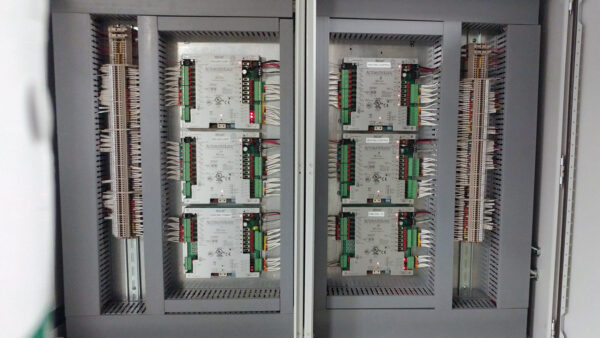
Ryan called his customer and asked if there was a maintenance person at the site with a cell phone. He immediately contacted them. The person was not familiar with the mechanical room so they established a two way video call over cellular phones. Ryan had him turn their camera on so he could see the room. He had the technician pan his camera left to right in the room. “There it is! Walk straight ahead, it’s the panel by that tank and those red pumps”, he directed. They walked over and opened the panel.
Ryan had him turn the camera on the control cards. He could see that the LED’s (Light Emitting Diodes) were illuminated on most of the cards as he expected except one. “See that card underneath the other card? Can you zoom in on that one?”. The LED's were not illuminated, he confirmed.
The technician measured 24 VAC at the terminals of the Card, which confirmed that the power supply was ok. “Switch your Volt Meter to Ohms”, Ryan requested. “Measure the ohms across that green resistor on the PCB" (printed circuit board), he said. “It’s an Open”, they reported. Based on the results of the troubleshooting, Ryan was able to determine what the root cause failure mode that was causing the effect using measurements.
Ryan dispatched ALC Tech, Connel Tauber, to the site with the tools and parts to fix the control board in the field. Connel was able to perform the field modification on the board and brought the control circuit back to life. He confirmed that all zones were communicating properly and reported to a relieved customer early that afternoon.
Root Cause Effect Analysis techniques allow us to troubleshoot complex systems logically using experience along with scientific and measured evidence that guide us to the failure mode. If you understand the Root Cause of the failure mode you can dispatch appropriate skill sets, tools and parts to the site to resolve the issue and get the system back up and running.
"Forced outages are a situation where you want the best of the best responding and delivering results. By partnering with Care Systems Services Ltd. you are getting the best service in the industry", Ryan Concluded.
Sharing is Caring
Share this on your favourite social media networks